
CVB 吹送式旋转阀
专为正压气力输送管道直连设计。
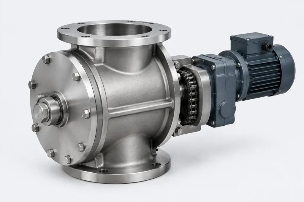
The CVB is a blow-through rotary valve: material enters the rotor pocket and is discharged directly into the conveying air stream, so the valve can sit inside a positive-pressure line without a separate drop leg.
The housing is machined after welding so the tip clearance stays nominal under pressure. Standard execution is SS304 or cast iron; SS316L, Hastelloy and internal coatings are available for abrasive or corrosive duty. Outboard bearings are standard, with air-purge shaft sealing and leakage gas venting as options.
Flanges can be drilled to DIN PN10, ANSI 150# or JIS 10K, and the rotor can be supplied open, closed, helical, adjustable-tip or reduced-volume for partial-pocket metering.
Specification
| Nominal size | DN 200 |
|---|---|
| Size range | DN 150 - DN 600 |
| Max differential pressure | 1.5 bar |
| Temperature range | -20 – 300 °C |
| Throughput | 0.6 - 6 t/h at 20 rpm |
| Motor power | 1.5 kW |
| Weight | 180 kg |
| Surface finish | Ra 0.03 - 0.08 μm (sanitary execution) |
| Flange drilling | DIN PN10, ANSI 150, JIS 10K |
| Lead time | 3-4 weeks ex works |
Max 1.5 bar differential, -20 °C to 300 °C (water-cooled above 200 °C).
Where this valve is used
Documents
- CV Series Datasheet PDF · 922.0 B
- CE Declaration of Conformity – CV Series PDF · 905.0 B
- CVB General Arrangement Drawing PDF · 894.0 B